Introduction
Most robotics systems fail not because of hardware limitations — but due to poor system architecture design. This is the uncomfortable truth that many engineers and project managers do not want to hear, because hardware is tangible, measurable, and easy to blame. Architecture failures are subtler, more systemic, and far more expensive.
My background is in mechatronics, so I approach a robot as the interaction of mechanical systems, electronics, sensors, control and software rather than as a software product with moving parts attached. That framing is the reason this article is about architecture at all: the failures worth writing about are rarely located in any one of those domains. They sit in the relationships between them, which is precisely where no single specialist is looking.
What follows is an argument from that discipline rather than a survey of field incidents. The five failure patterns below are the ones that follow structurally from getting those relationships wrong — which is why they recur across otherwise unrelated platforms. The hardware changes; the architectural mistakes are the same shape every time.
This article breaks down the five most critical architecture failure points in robotics systems — and what the correct design approach looks like.
1. Over-Centralized Control Systems
The most common architecture mistake in robotics is building everything around a single, centralized control unit. One controller handles motion planning, sensor processing, communication, safety logic, and HMI interaction simultaneously.
This design pattern is intuitive — it seems simpler to manage. But in practice, it is architecturally fragile and operationally dangerous.
The Problems with Centralized Control:
- Single point of failure: If the central controller crashes, the entire system goes down. There is no graceful degradation — just a full stop.
- High latency bottlenecks: When one processor is responsible for everything, high-priority tasks (real-time motion control) compete with low-priority tasks (data logging, UI rendering). This introduces jitter and latency into deterministic control loops.
- No distributed intelligence: The system cannot make local decisions at the subsystem level. Every decision must route through the central controller, creating unnecessary communication overhead.
The Correct Approach: Distribute control responsibilities across dedicated subsystems. Motion control runs on a dedicated real-time controller. Safety logic runs on an independent safety PLC. Communication and data handling run on a separate compute unit. Each subsystem operates autonomously within its domain and communicates only what is necessary upstream.
2. Ignoring Real-Time Constraints
Robotics is not just software engineering. This is a fundamental truth that teams with a purely software background often learn the hard way — after a system is already deployed and failing in the field.
Real-time systems have hard timing requirements. Motion control loops typically require deterministic execution every 1–10 milliseconds. Sensor fusion algorithms need precise timestamping. Safety responses must execute within defined response windows.
The Most Common Real-Time Mistake: Using cloud-based or network-based decision-making for actions that require real-time response. Sending sensor data to a cloud API, waiting for a response, and then commanding the actuator. This introduces network latency, jitter, and unpredictable response times into a system that requires determinism.
Consequences:
- Delayed motion response causing mechanical collisions
- Unsafe behavior in safety-critical systems
- Oscillation and instability in closed-loop control systems
- Intermittent failures that are impossible to reproduce and diagnose
The Correct Approach: Establish a strict architectural boundary between real-time and non-real-time domains. Real-time control (motion, safety, sensor feedback) executes locally on deterministic hardware. Non-real-time operations (analytics, cloud sync, UI updates) operate asynchronously and never block the control loop. These domains communicate through well-defined, non-blocking interfaces.
3. Poor Sensor Fusion Design
Modern robotics systems rely on multiple sensors simultaneously — encoders, IMUs, cameras, LiDARs, force sensors, proximity switches. When these sensors are not properly integrated at the architecture level, the system makes decisions based on inconsistent or contradictory data.
Common Sensor Fusion Failures:
- Inconsistent sensor timing: Sensors sampling at different rates with no synchronization mechanism. A 100Hz encoder and a 30Hz camera providing position data that is temporally mismatched.
- No synchronization architecture: Sensor data arriving at the fusion layer with different timestamps, latencies, and reference frames — with no mechanism to align them.
- Missing filter strategy: Raw sensor data fed directly into control loops without noise filtering, outlier rejection, or Kalman-based estimation. Every sensor spike becomes a control command spike.
- Single-sensor dependency: Critical decisions based on a single sensor with no redundancy or cross-validation. When that sensor drifts or fails, the system either acts on bad data or fails completely.
The Correct Approach: Design a dedicated sensor fusion layer in the architecture. Define a common time reference across all sensors. Implement hardware or software synchronization. Use proper filtering (Kalman filter, complementary filter, or median filtering depending on the application). Cross-validate sensor readings where safety-critical decisions are involved.
4. No Fault Isolation Strategy
In a poorly architected system, a single component failure cascades into full system failure. A sensor reading returns an unexpected value. The control algorithm receives bad input. The output command exceeds safe limits. The safety system triggers an emergency stop. The entire line goes down.
This failure cascade is not the result of bad luck — it is the result of a design that has no fault isolation boundaries.
What Fault Isolation Means in Practice:
- A mechanical failure in one axis should not crash the controller for all axes
- A communication timeout on one sensor should trigger a defined degraded mode — not a full system halt
- A software exception in the data logging module should not affect the real-time control loop
- A network failure to the cloud should not disable local machine operation
The Correct Approach: Define fault domains explicitly in the system architecture. Each subsystem must have a defined failure mode and a defined response to that failure mode. Implement watchdog timers at every critical layer. Design explicit safe states for every failure scenario — not just the obvious ones. Test fault injection scenarios before deployment.
5. No Redundancy in Safety-Critical Paths
Many robotics systems treat safety as an add-on — something bolted onto the architecture after the core system is designed. This is architecturally backwards and creates systems that cannot meet industrial safety standards (IEC 62061, ISO 13849) without major redesign.
Safety-critical paths — emergency stop circuits, overtravel limits, collaborative robot force monitoring — require hardware-level redundancy, not software-only implementation. A software safety check that runs on the same processor as the motion control loop is not an independent safety layer. It is an illusion of safety.
The Correct Approach:
- Deploy an independent safety PLC (Pilz, Sick, Siemens Safety) separate from the main controller
- Implement dual-channel safety circuits for E-stops and safety doors
- Use safety-rated encoders and drives where required by risk assessment
- Never route safety logic through the standard communication bus — use dedicated safety networks (PROFIsafe, FSoE)
The Better Architecture Framework
A robust robotics system architecture separates concerns cleanly across well-defined layers:
- Real-time control layer: Dedicated RTOS or safety PLC handling motion and safety. Deterministic, isolated, no shared resources with other layers.
- Edge intelligence layer: Local compute handling sensor fusion, anomaly detection, and local decision-making. Communicates with control layer via non-blocking interfaces.
- System management layer: Handles communication, diagnostics, remote monitoring, and non-real-time coordination.
- Cloud/enterprise layer: Analytics, reporting, AI model updates, fleet management. Asynchronous, never blocks local operation.
Each layer has clearly defined responsibilities, fault isolation boundaries, and communication protocols. Failures are contained. Redundancy is designed in from the start.
Why the boundaries are where things break
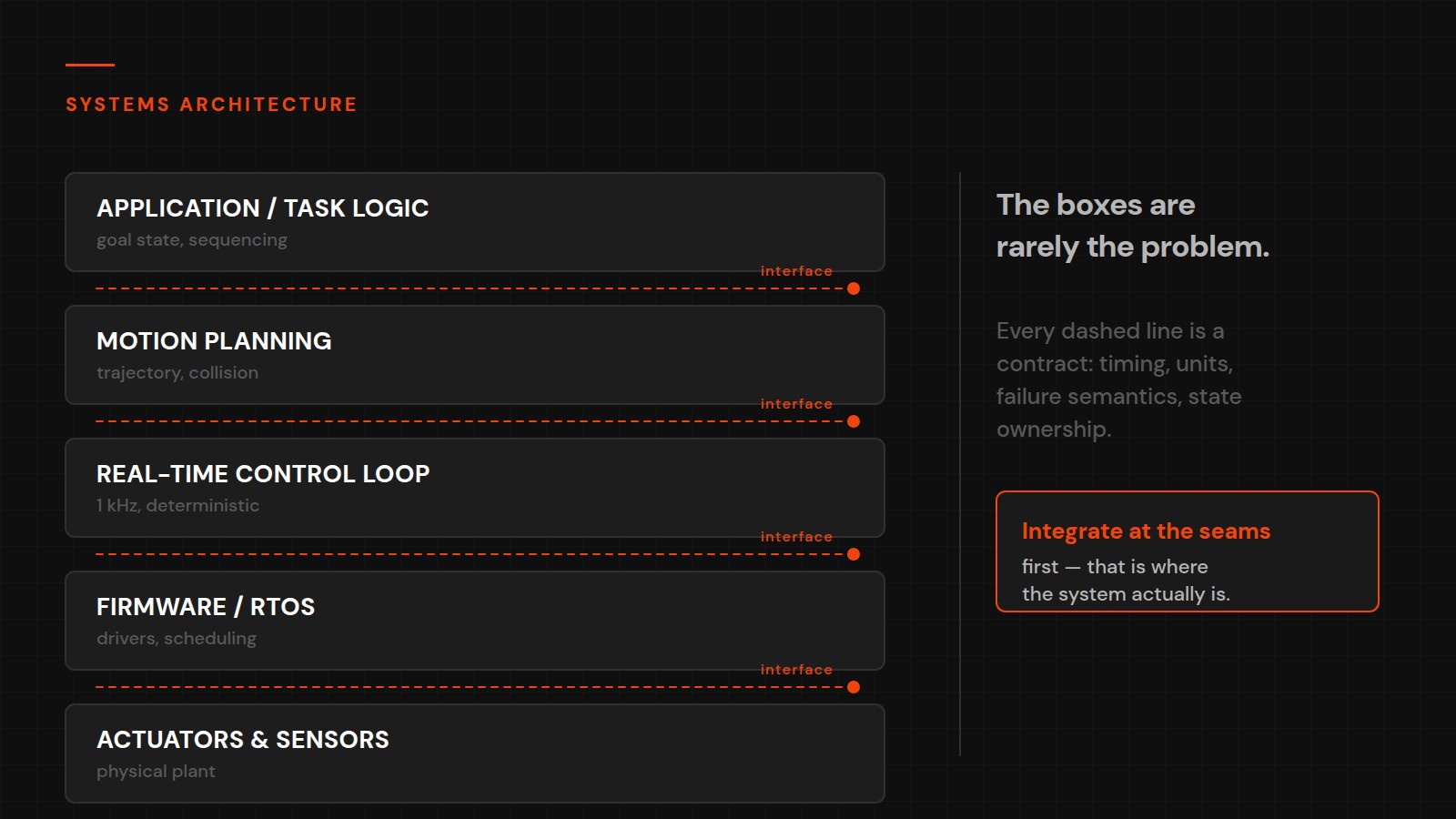
If there is a single idea underneath all five of the failure patterns above, it is this: I do not treat hardware, embedded control, cloud software and AI as separate layers that happen to be connected. The interesting engineering problems almost always happen at the boundaries between them, and boundaries are exactly what a conventional division of labour leaves unowned.
Consider how each of these failures actually presents. Over-centralised control is a boundary between decision-making and actuation drawn in the wrong place. Ignored real-time constraints are a boundary between a general-purpose computing environment and a process with deadlines. Poor sensor fusion is a boundary between physical measurement and software interpretation, where the software quietly assumes more than the sensor can deliver. Missing fault isolation is an absent boundary — a failure that should have been contained propagates because nothing was designed to stop it.
None of these are visible from inside a single discipline. The mechanical engineer sees a mechanism that meets spec. The firmware engineer sees a loop that closes. The application developer sees an API that returns. Every component is defensible on its own terms, and the system still fails, because the failure lives in an assumption that two components each expected the other to hold.
The practical consequence for how I work is an ordering rule: design from the system requirements and the failure modes first, then select the technology. Choosing components first and discovering the architecture afterwards is how boundaries end up being set by datasheets and library APIs rather than by the requirements of the machine. Once the failure modes are written down — what happens when this sensor stops reporting, when this link drops, when this actuator stalls, when power is interrupted mid-motion — the architecture that survives them is usually a much narrower set of options than it first appeared.
Conclusion
Robotics systems fail because of architecture, not hardware. Over-centralised control, ignored real-time constraints, poor sensor fusion, missing fault isolation and inadequate safety design are the patterns that recur — and they recur because each one is a boundary problem, not a component problem.
The solution is not more hardware budget. It is a disciplined approach to systems architecture — defining layers, boundaries, fault domains, and safety paths before writing a single line of code or specifying a single component. Get the architecture right, and the hardware can perform to its potential. Get it wrong, and no amount of hardware quality will save you.